INTERNAL FUSES
The capacitors can be provided with internal fuses, where each capacitive element is provided with a fuse set in series with the
element; if the capacitive element breaks the fuse trips, disconnecting the broken element from the unit that is not involved in the short circuit, thereby making it possible for the capacitor to work. The fuse tripping then produces a reduction in capacitance; if a number of fuses trip, the variation must be such as to anyhow keep the resulting total capacitance within the limits of tolerance prescribed by the reference standards. This system offers the obvious advantage of being able to operate also with units in which there are broken elements (respecting the above criteria); however there are construction limits due to the need to have a fair number of capacitive elements connected in parallel for each series branch, so that disconnecting the broken element has no effect on the remaining elements in terms of overvoltage and overcurrent.
EXTERNAL FUSES
The medium voltage capacitors and banks can be provided with external fuses to protect against faults caused by short-circuiting. External fuses used by Enerlux Power Srl:
HRC FUSES
H.R.C. fuses are normally used to protect small banks and/or three-phase capacitors, designed in accordance with DIN and IEC standards for protection against thermal and dynamic effects, caused by short circuit current exceeding the tolerated value in magnitude and duration.
The main characteristics of H.R.C. fuses are:
H.R.C. fuses are the best solution in situations where using other protection systems would re- quire an excessive cost compared to that of the whole system.
To obtain the maximum current limitation, and therefore the best protection, the rated current of the chosen fuse must be selected at the lowest possible level compared to the value of the cur- rent equal to about 2 times In.
The fuse cartridge striker, besides performing the function of signalling tripping, can be associated with the device for turning off the operating- disconnecting switch and/or with the external indicator device. Besides H.R.C. fuses, accessories can be supplied such as the specific fuse holder bases and the trip signalling devices.
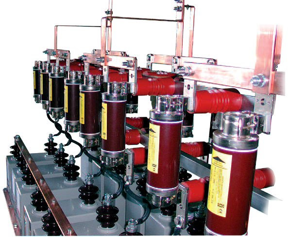
EXPULSION FUSES
Expulsion fuses are normally used to protect banks with high powers usually installed outside, where there are many units in parallel. Using expulsion fuses is a practical cost-effective and functional system since, in case of failure:
- only the unit involved is excluded, keeping the sy- stem in service, making it possible to schedule repla- cement;
- searching for the affected unit is easy and fast as it is easy to see thanks to the expulsion device, thereby making it possible to minimize the search time (see figure R);
- the fuse can be reused by changing only the inter- nal cartridge element.
We should point out that system operation, in the event of failure and ensuing exclusion of one or more units, is only permissible if the increase in vol- tage on the remaining capacitors is less than 10% (minimum number of 10 units in parallel per phase). If use involves a smaller number of units in parallel, the bank of capacitors must be disconnected from the network to avoid damage to the other units that are still integral.
It is recommended to use expulsion fuses on banks with a max power of approximately 5 Mvar; this va- lue is based on the need to prevent the current due to the discharge of the energy stored in the units connected in parallel with the defective unit cau- sing the container to break.
For greater required powers it is however possible to use expulsion fuses, inserting more series groups on the same phase with an according increase in the overall power, but limiting the discharge energy in parallel compared to layouts with only parallel groups.
Protection by using expulsion fuses must anyhow always be associated with unbalance protection.
The only protection against overcurrents does not ensure sufficient protection against internal unit breakdown; additional protection is therefore ne- cessary, especially when many units are involved. The optimal and efficient solution to guarantee the effectiveness and correct monitoring of the banks of capacitors is unbalance protection. There are several types of unbalance protection, the one most widely used involves measuring the current unbalance between the two star centers; the operation of this protection is based on checking the symmetry of the two star centres of the bank.
In a balanced three-phase system the current between the two star centers is practically zero, whereas if elements or units break down they shift with circulation of the residual current; installing a current transformer between two star centers it is possible to measure this residual current and, with a special relay, it is possible to promptly perform operations such as releasing the main switch, opening circuits or signaling a problem without causing damage to the good units. This very sensitive system is also able to detect failure of a single element and this prevents the remaining installed components from getting damaged; in addition, the protection and operating devices work on breaks in loads at nominal levels and not at short circuit levels.
Unbalance protection therefore comprises a current transformer and an homopolar residual current relay.
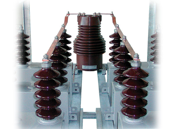
CURRENT TRANSFORMER FOR UNBALANCE PROTECTION
The function of the current transformer is to measure the currents coming from the unbalance of the two stars of the capacitor bank and to isolate neutral at the same level as the mains voltage. Enerlux Power Srl uses current transformers for indoor and outdoor installations; on request other types of transformers can be installed with different ratios, insulating voltage, performances, etc...
RELAY FOR UNBALANCE PROTECTION
The unbalance protection relay is a homopolar residual current relay, insensitive to harmonics with independent time. This is a relay made with a conventional system that due to its characteristics of high reliability, easy settings and inexpensiveness is the one most widely used. The relay is equipped with a trip threshold that is associated with a relay with double output contacts in the standard version; for the protection of banks with high powers or where required, it is recommended to use two relays to create two thresholds (alarm and trip).
OVERCURRENT PROTECTION
The use of a protection against overcurrents is usual- ly required on capacitor banks, additionally to unbalance protection; this protection is normally realized with No 3 line current transformers, No 1 unbalance current transformer and proper relay.
Protection functions can be realized with:
Due to the different types of available relays, we advise to contact Enerlux Power Srl technical department that will provide related technical information.
FAST DISCHARGE DEVICE
These are devices suitable for fast discharge of capacitor banks and batteries after disconnection from the network, reducing the residual voltage at the terminals of the bank extremely quickly (approximately 10÷15 seconds), differently from standard systems where the discharge time is of several minutes
This solution offers the following advantages:
We should point out that the operation of the fast discharge device must anyhow contemplate the thermal effects of the discharge currents crossing it; it is therefore wise to wait at least 5 minutes after two fast discharges before reconnecting the bank to the network.